.banner{display:none;}

Saturday 28 December 2013

What is SMPS...(Switch Mode Power Supply)

                                     How to Easily Understand The Functions
                                Of Switch Mode Power Supply 


Troubleshooting linear power supply was quite easy as compare to switch mode power supplies (SMPS). AC voltage enters to the primary side of linear transformer and then converted the AC into a lower or higher AC voltage depending on the secondary winding. The output AC voltage is then rectified and filtered by a diode and capacitors to produce a clean DC voltage.
If there is a problem in the linear transformer circuit, I can say that it is very easy to locate the fault. This is somehow different in the case of a switch mode power supply. The designs were complicated and some technicians found it quite hard to fully understand how the switch mode power supplies work.
The working principle of switch mode power supply is different from the linear type. First the AC voltage will enter to a full wave rectifier (bridge rectifier) which produces an uneven DC output and then filtered by a large capacitor (usually 220 micro farad and up to 450 volts).


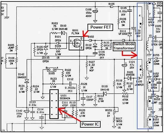
The clean DC voltage will then enter to start up resistors and to the input of switch mode power transformer. Once the voltage passed through the high ohms resistor (start up resistors) the voltage would drop to a value where it then enters to the VCC supply pin of Pulse width modulation IC.


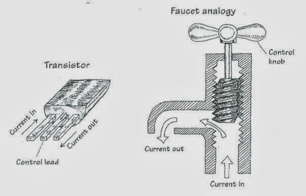
Once the PWM IC received the voltage it will output a signal to drive the transistor (or FET) and produces a changing in magnetic field in the transformer primary winding. The changing magnetic field induces voltage in the secondary windings.
Each of these AC voltage produced by the secondary windings is then rectified, filtered, and regulated to produce a clean DC voltage. One of the main DC output voltage is the B+ that supply to flyback transformer (for TV and Monitor Circuit)


The output from the B+ voltage supply is then connected, through a “feedback” loop (which consist of optoisolator ic and an error amplifier TL431 IC), back to the PWM IC. When the voltage from the B+ supply rises or drop a bit, the PWM IC will act to correct the output.
You must ask your self what is the purpose and its function of the components in the SMPS circuit and how to check them if they fail. Find out the function of these components in SMPS circuit:
Bridge rectifier,

Filter capacitor, Start up resistors Chopper/Power FET
Pulse Width Modulation (PWM IC) Current sense resistor Switch mode power transformer Optoisolator/optocoupler Error Amplifier IC (TL431) Secondary diodes Secondary filter capacitors


Push yourself further by searching the internet for the datasheet of a PWM IC part number. For example, UC3842 PWM IC is mostly used in SMPS. Do you know what the function of pin 5 of this IC is? Do you know which pin is the supply voltage (VCC)? Do you know what is the actual voltage that enters to the IC? Do you know which pin that drives the power FET? Can I get a replacement for this IC? And so on………
Let’s take a soldier as an example. Soldiers not only good in handling rifle but also knows all the details about it. They know how to dismantle and assemble back their rifle fast (imagine in the middle of war the rifle jammed-they can repair it fast). They know how much each bullet cost, how far the shooting distance, how big is the diameter of the bullet, how many cm the length of the bullet and so on. Hope you don’t get bored with the soldier’s story, did you get the ideas?


Any SMPS that comes across my repair bench, I would not immediately repair it, in fact I will take couples of minutes to analyze the circuit design and see it from all angles before I begin to repair. Troubleshooting SMPS is not limited to only one procedure in fact many electronic repairers have their own unique ways and methods to solve SMPS problems. Some prefer to use light bulb to isolate SMPS faults while others like to use resistors. Troubleshooting SMPS is fun and flexible but in some cases could make you get very frustrated too.
Remember, don’t limit yourself to only one or two sources to get you understand and be able to repair SMPS. If you have the budget, get the books that have related to SMPS repair-study and start doing practical about it. Share your problems with other fellow electronic repairers and the most important thing is don’t give up. There’s lot of mountain in the journey of our live and you yourself have to climb and conquer it. All the best!

Monday 23 December 2013

WHT IS AN OLED...?

OLED Components


How do OLEDs Emit Light?

OLEDs emit light in a similar manner to LEDs, through a process calledelectrophosphorescence.
The process is as follows:
  1. The battery or power supply of the device containing the OLED applies a voltage across the OLED.
  2. An electrical current flows from the cathode to the anode through the organic layers (an electrical current is a flow of electrons). The cathode gives electrons to the emissive layer of organic molecules. The anode removes electrons from the conductive layer of organic molecules. (This is the equivalent to giving electron holes to the conductive layer.)
  3. At the boundary between the emissive and the conductive layers, electrons find electron holes. When an electron finds an electron hole, the electron fills the hole (it falls into an energy level of the atom that's missing an electron). When this happens, the electron gives up energy in the form of a photon of light (see How Light Works).
  4. The OLED emits light.
  5. The color of the light depends on the type of organic molecule in the emissive layer. Manufacturers place several types of organic films on the same OLED to make color displays.
  6. The intensity or brightness of the light depends on the amount of electrical current applied: the more current, the brighter the light.


Types of OLEDs: Passive and Active Matrix


There are several types of OLEDs:
  • Passive-matrix OLED
  • Active-matrix OLED
  • Transparent OLED
  • Top-emitting OLED
  • Foldable OLED
  • White OLED
Each type has different uses. In the following sections, we'll discuss each type of OLED. Let's start with passive-matrix and active-matrix OLEDs.

Passive-matrix OLED (PMOLED)

PMOLEDs have strips of cathode, organic layers and strips of anode. The anode strips are arranged perpendicular to the cathode strips. The intersections of the cathode and anode make up the pixels where light is emitted. External circuitry applies current to selected strips of anode and cathode, determining which pixels get turned on and which pixels remain off. Again, the brightness of each pixel is proportional to the amount of applied current.
PMOLEDs are easy to make, but they consume more power than other types of OLED, mainly due to the power needed for the external circuitry. PMOLEDs are most efficient for text and icons and are best suited for small screens (2- to 3-inch diagonal) such as those you find in cell phonesPDAs and MP3 players. Even with the external circuitry, passive-matrix OLEDs consume less battery power than the LCDs that currently power these devices.

Active-matrix OLED (AMOLED)


AMOLEDs have full layers of cathode, organic molecules and anode, but the anode layer overlays a thin film transistor (TFT) array that forms a matrix. The TFT array itself is the circuitry that determines which pixels get turned on to form an image.
AMOLEDs consume less power than PMOLEDs because the TFT array requires less power than external circuitry, so they are efficient for large displays. AMOLEDs also have faster refresh rates suitable for video. The best uses for AMOLEDs are computer monitors, large-screen TVs and electronic signs or billboards.


OLED TUTORIAL


What is an OLED?

Organic Light Emitting Devices are solid state devices comprising a thin electroluminescent organic (carbon-based) semiconductor layer that emits light when electricity is applied by adjacent electrodes
•In order for light to escape from the device, at least one of the electrodes must be transparent
Intensity controlled by amount of current applied
Color of light determined by emissive material used   
Organic material can be deposited by vapor phase or solution deposition
Intensive research into creating more efficient materials and structures

Structure of OLED Stack...


Why Are OLEDs Appealing?

SSL FEATURE


  1. Higly Efficient
  2. Long Life
  3. Durable
  4. No HarmFul Substance
  5. Low Voltage
  6. Instant On
  7. Dimmable
  8. Colour Tuneable

                                                 
Why Are OLEDs Appealing?


  1. Diffuse, low brightness, large area
  2. Any Colour Shape
  3. Thin Light Weight
  4. Flexible
  5. Transparent
  6. Mirror Surface

Unique Features...?


  ANY COLOR SHAPE

TRANSPARET LIKE NOVALED
DIFFUSE LIGHT  THIN (LUMIOTEC)
                                                                       LIKE A MIRROR

OLED Potential 

OLED Panel Status & Targets


Sunday 22 December 2013

Changhong LCD TV Repairing Tips


21K39PH – 21K51PH – PF2114PH – PF2115PH

DEAD SET

R528, FUSE, R502, L502, L503, V512, VD515,
BRIDGE RECTIFIER DIODES
CHANGING CHANNEL NOT FINE TUNED
DEFECTIVE DIODE NEAR JUNGLE IC
NO MENUR733 10K Ohms OPEN
ADJUST SCREEN RETRACE GREEN HAVE SCREEN
GOOD B+ STANDBY ONLY NO HIGH VOLTAGE OUT
PUT VIDEO IN AND OUT = GOOD = GOOD SYSTEM IC AND JUNGLE GOOD
AUTO PROGRAM THE UNIT CHANNEL CHANGING BUT NO SOUND
= DEF JUNGLE IC
BURNT RX02
RXO1 NOT MATCH THE ORIGINAL
OVERHEAT H-OUT
LEAKAGE H-OUT OR CAPACITOR
STANDBYEEPROM, SENSOR
PINCUSIONING CAPACITOR BLOWN
RM11C SHORTED
WHITE SREEN
JUNGLE IC,( LA76814K )
NO PICTURE
TUNER, DEMODULATION IC, IF TRANSFORMER, JUNGLE IC, SYSTEM IC
VIDEO PRESS MANY TIMES PICTURES GONE
BC SUPPLY UP TO 7.5 VOLTS , REPLACE 8.2V DIODE AS BLOCKING DIODE TO PRODUCED 0.28V BASE OF R G B
ABNORMAL VERTICAL ONE LINEHANG PIN#7 OF SYSTEM IC IF VERTICAL RETRACE APPEARS ON SCREEN ,
V702 = A1015 DEFECTIVE
BURN THE REGULATORC3807 AND VD515 OPEN
NO MENUR722, R723, V704, V703
OSCILATE NO RASTER BLACK SCREEN
CHECK: VIDEO OUT- GOOD
- VIDEO IN – GOOD
- V704 & V703 COLLECTOR = 5VOLTS
- RESISTOR BIAS 10K Ohms
- R725 & R733 OPEN
- DEF V704
NO HEATER
RF481, FLYBACK TRANSFORMER,
HORIZONTAL LINE OUTPUT TRANFORMER,
HORIZONTAL LINE OUTPUT TRANSISTOR,
HORIZONTAL DRIVE TRANSISTOR, AND
JUNGLE IC ( LA76814K )
NO VIDEO INCPU OR SYSTEM IC DEFECTIVE
RETRACE LINEV901, V902, V903, AND
COLOR DRIVE TRANSISTORS
ABNORMAL VOLTAGERF551, VD586, V582, V583
NO SIGNAL
TUNER ( TDQ-6F2M )
IF TRANSFORMER, SAW TOOTH FILTER,
CHECK 5 VOLTS AND 45 VOLTS
NOTE: 45 VOLTS MUST BE 21-22.5 VOLTS VCC,
5 VOLTS MUST BE 4.8 VOLTS IF
45 VOLTS MEASURES 31 VOLTS
IT MEANS NO 5 VOLTS SUPPLY OR LOOSE CONTACTS,
MEMORY MAY POSSIBLE
JUNGLE DEFECTS IF NO RASTER
PF2914PH NOT OSCILATESCHECK:
POWER SUPPLY TO ACTUAL
- NO 5V-2
- 8V = 1V ONLY
- NO STANDBY VOLTAGE
- SUSPECTED AREAS:
- BCJA18D OSCILATOR DEFECTIVE
- CPU
- JUNGLE IC
- MEMORY
21F SERIES

CAUSE AND DEFECTS
OSCILATE NO PICTURE
CHECK- 3.3 VOLTS ( V512 ) = A1569 TRANSISTOR,
- PIN # 33 OF IC BUS OMS 837X ,
PIN# 54, 56, AND 61 IS 3.3 VOLTS
- HANG PIN# 10 OF JUNGLE IC
IF TV SET POWER UP DEFECTIVE JUNGLE IC
- V805 =A1015
- HANG UP C839
- PIN#33 JUNGLE IC 0.48V TO H-DRIVE BASE
- 1200MGhz REPLACE IF HIGH VOLTAGE TOO HIGH
OUTPUT OR NO OUTPUT
- C824A DEF
NO PICTURE BLACK SCREEN
OSCILATE NOT POWER ON
– CHECK
- +B 115 VOLTS.
- COLLECTOR OF HORIZONTAL OUTPUT 115V UP TO 118.5V
- BASE OF H-OUT 0.22VOLTS IF NOT FIND OTHER CAUSE
- V810, V811, D831
- COLLECTOR OF V810 = 1.98V IF NOT D831 LEAKAGE
- PIN# 45 OF IC BUS OPEN IF VOLTAGE EXCIST TO 4.5V
- HANG UP THE C839 THEN TRY TO RUN THE TV SETS IF IT WORKS PROPERLY REPLACED THE D831 OR OTHER RELATED X-RAY PROTECTION CICUITS
oscilate only not power on
CHECK +B 115 TO 118.5 VOLTS, STANDBY VOLTAGE 90 TO 93 VOLTS
- 3.3 VOLTS OF PIN# 45, 54, 56, & 61 IF GOOD CHECK
- 3.3V BECOME 1.6V IF ATTACHED TO JUNGLE IC JUNGLE IC
REPLACE THE A1569 3.3V REGULATOR
- MEMORY VOLTAGE 5V, 4.56V, & 4.58V IF GOOD
- REPLACE EEPROM 24C16
- AUDIO DEMODULATOR IC( N106 ) = TDA9859
- DEMODULATION IC ALSO RESPONSIBLE FOR THE OSCILATION
OR SWITCHING LOW VOLTAGE SECTION
- REPLACE THE TDA9859 IF DEFECTIVE
HANG PIN#15, 16, 17 &18
- CHECK ALSO 5V REGULATOR 7805
NO LEFT AUDIO
CHANGE EEPROM

NO VIDEO INPUT SIGNAL AND SOUND WITH AIREAL OR CABLE SIGNALV213 DEFECTIVE = C1815
R309 OPEN 1K OHMS
NO AIREAL SIGNAL WITH VIDEO INPUT SIGNAL
V214 DEFECTIVE = A1015,
N808=LM317T 8.2 VOLTS REGULATOR,
C824A= 35V/1000uf , C861= 16V/1000uf
RAINBOW COLOR APPEARS ON SCREEN
REPLACE VERTICAL IC

BURN RY22SHORTED TO GROUND THE CRT SOCKET AND
NEED TO REPLACED A NEW ONE
IF NO GREEN COLOR OR VOLTAGE UP TO 185V VY06 NEED TO REPLACE
STANDBY NO OTHER ACTION OF THE TV SETHANG UP C839, IF IT WORKS D831 DEFECTIVE AND
OTHER RELATED X-RAY PROTECTION CIRCUITS.
- TRY TO CHANGE EEPROM,
- AUDIO DEMODULATOR
- A1569=3.3V REGULATOR
- REGULATOR = STR G8653 OR 8656
OSCILATE NO PICTURE NO HEATER
NO VOLTAGE IN D831 CHANGE IC BUS AND MEMORY
- 190V = 150 ONLY AND ABNORMAL
- 30V GOOD IF FLYBACK HANG UP BUT DECREASE IF CONNECTED
- H-DRIVE AND PRE-DRIVE GOOD
- R841 CHANGE VALUE = 15K BECOME 25K Ohms
- R260 OPEN

OSCILATE AUTO PICTURE
LOOSE CONTACT IN JUNGLE IC BUS NEED RESOLDER OR CHANGE IC
OSCILATE NO PICTURE BLACK SCREEN WITH HEATER
CHECK: R G B SUPPLY FROM JUNGLE IC BUS 2.0 OR 1.98V TO 2.53V
IF IT EXCEEDED OR 3.0
CHECK 8.2 VOLTAGE SUPPLY FROM LM317T AND
THE FILTER CAPACITOR
L805 MUST 8.2 VOLTS IF ITS ALL GOOD
REPLACE THE JUNGLE IC MAY DEFECTIVE
R867 DEFECTIVE AND D838
AUTO SHUT ON AND OFF H-OUT NOT RUN
H-DRIVE TRANSISTOR C2688 LEAK
VERTICAL RETRACE UPPER LINE
R402 CHANGE VALUE
AUTO SHUT ON BLUE BACK AND NO OTHER ACTIONS
JUNGLE IC DEFECTS
OSCILATE NOT POWER UP STILL STANDBY MODE
JUNGLE IC DEFECTIVE
POWER BLINKS ONLY BACK TO STANDBY MODE680 Ohms = R804 OPEN,
STR G8653 LEAKGE,
EEPROM
D822 SHORTTED= RG2,
NO PICTURE BLACK SCREEN BUT HAVE MENU
LM317T SECTION 8.2 VOLTS DEFECTIVE
OUT OF HORIZONTAL SYNCR255 SHORTED TO GROUND
C388 DEFECTIVE
JUNGLE IC

29F PIN CUSTIONING DEFECTS
EW SECTION CANT ADJUST,
68K Ohms =R409 OPEN
29F18 RETRACE LINE UPPER SIDE
R403 CHANGE VALUE
29F18 BURN SUPPLY TO HEATER & G2 BRIDGE CAPACITOR
CHANGE FLYBACK
FLECKERING WHEN AUTO PROGRAMR841 CHANGE VALUE,
C206 LEAKAGE
VERTICAL NOT ENOUGHR403 CHANGE VALUE 0.33Ohms TO 0.15 Ohms
LIGHTNING EFFECTS
C206A OPEN OR SHORTED AND
R841 CHANGE VALUE
LOW VOLTAGE B+V802 COLLECTOR TO EMITTER OPEN
LOW VOLTAGE BLINKING DEFECTSB+ ABNORMAL = R804 680 Ohms CHANGE VALUE AND
C810 LEAK
PF29F15PH AND PF29F18PH WIDE VERTICAL OR STRETCHED
MEASURE THE VD501 OR VD402 & VD437
IF GOOD WHILE HANG UP BUT
SHORTED WHEN ATTACHED= VERTICAL IC DEFECTIVE
SMALL RETRACE APPEARS ON SCREEN R G BREPLACE JUNGLE IC
NO SIGNAL
TUNER,
SAW TOOTH FILTER, JUNGLE IC,
NO PICTURE WITH SOUNDS
H-DRIVE OPEN
INTERMITTENT DEADSET
H TRANSFORMER LOOSE CONNECTION
NO RIGHT AUDIODEFECTIVE AUDIO PROCESSOR TDA9859
PRESS ANY BUTTONS EVEN REMOTE MENU APPEARS ON SCREEN
JUNGLE IC DEFECTIVE
NO COLORMEMORY AND 1200MGhz DEFECTIVE
H1418PH IN COMPLETE CHANNELSTUNER OR JUNGLE IC
ONE CLICK ONLY AND LIGHT INDECATOR BLINKS ONLYCHANGE MEMORY
NO SIGNAL RECIEVEDCHECK: VIDEO IN = GOOD- TUNER
- SHORTING THE SAW FILTER WILL
DETECTS OR ISULATE THE CAUSE ETHEIR
JUNGLE OR TUNER SECTION IF RASTER APPEARS JUNGLE OK
- MEMORY= GOOD
- TUNER = GOOD
- FR AMP = GOOD
- DEMODULATION = GOOD
- 3.3V= GOOD
- 5V = GOOD
- 3.39V = GOOD
- 22V = GOOD
- 8.2 VOLTS MAY LEAK
H1418PH WHITE VERTICAL LINES STRIPSCHECK: VIDEO OUT = GOOD
- RGB VOLTAGE = 6V INSTEAD OF 3.0 VOLTS
- RGB AMP = 55V- 190V = GOOD
- VD301= A1015 DEFECTIVE
STANDARD CRT TUBE SHUT OFF AFTER 30 MINUTES TO 2HrsLY01 NOT CONNECTED AN
GROUND TO HEATER GROUND OPEN
AUTO PROGRAM = GOOD BUT NO CHANNEL APPEARS AFTER FINISH
SERVICE MODE NOT FUNTION TOO
REPLACE THE MEMORY
B+ GOOD BUT NO FLYBACK B+R501 OPEN AND H-OUT
14F98PH BURN R406R406 = 10 Ohms
REPLACE D402
STANDBY ONLYC823 DEF
AUTO POWER ON NO PICTURE
MEMORY DEFECTIVE
BLURD PICTURE
G2= 50 VOLTS ONLY
CY04 = OPEN
BURN R821
MEMORY REVERSED CONNECTION
OVERHEAT H-OUT
LEAK H-OUT
C502 &C501 = DEFECTIVES
NO SECONDARY VOLTAGECHECK: PHOTO COUPLER
- REGULATOR
- B+ DIODE RG2
- R803 CHANGE VALUE= 0.27 Ohms
- D805 = RU2 OR AK03
- C808= 2KV/680P

Saturday 21 December 2013

COLOUR CODING OF RESISTENCE...


The 4-band code is used for marking low precision resistors with 5%, 10% and 20% tolerances. Identifying the value will become easy with a little practice, as there are only a few simple rules to remember: The first two bands represent the most significant digits of the resistance value. Colors are assigned to all the numbers between 0 and 9, and the color bands basically translate the numbers into a visible code. Black is 0, brown is 1, red is 2 and so on (see the color code table below). So, for example, if a resistor has brown and red as the first two bands, the most significant digits will be 1 and 2 (12). The third band indicates the multiplier telling you the power of ten to which the two significant digits must be multiplied (or how many zeros to add), using the same assigned value for each color as in the previous step. For example, if this band is red (2), you will multiply it by 102 = 100 (or add 2 zeros). So, for the resistor we used in the previous example, the value would be: 12 x 100 = 1200Ω (1.2kΩ). Note: If the multiplier band is gold or silver, the decimal point is moved to the left by one or two places (divided by 10 or 100). The tolerance band (the deviation from the specified value) is next, usually spaced away from the others, or it's a little bit wider. A color is assigned to each tolerance: gold is 5%, silver is 10%. 20% resistors have only 3 color bands

Basic Electronics Part2


Diode

•A diode is a 2 lead semiconductor that acts as a one way gate to electron flow.
– Diode allows current to pass in only one direction.
•A pn-junction diode is formed by joining together n-type and p-type silicon.
•In practice, as the n-type Si crystal is being grown, the process is abruptly altered to grow p-type Si crystal. Finally, a glass or plastic coating is placed around the joined crystal.
•The p-side is called anode and the n-side is called cathode.
•When the anode and cathode of a pn-junction diode are connected to external voltage such that the potential at anode is higher than the potential at cathode, the diode is said to be forward biased.
–In a forward-biased diode current is allowed to flow through the device.
•When potential at anode is smaller than the potential at cathode, the diode is said to be reverse biased. In a reverse-biased diode current is blocked.


Diode: How it Works —I

•When a diode is connected to a battery as shown, electrons from the n-side and holes from the p-side are forced toward the center by the electrical field supplied by the battery. The electrons and holes combine causing the current to pass through the diode. When a diode is arranged in this way, it is said to be forward-biased.


Transistor

A three lead semiconductor device that acts as: – an electrically controlled switch, or
– a current amplifier.
• Transistor is analogous to a faucet.
–Turning faucet’s control knob alters the flow rate of water coming out from the faucet.
–A small voltage/current applied at transistor’s control lead controls a larger current flow through its other two leads.


               Transistor Types: BJT, JFET, and MOSFET


• Bipolar Junction Transistor (BJT)
– NPN and PNP
• Junction Field Effect Transistor (JFET)
– N-channel and P-channel
• Metal Oxide Semiconductor FET (MOSFET)
– Depletion type (n- and p-channel) and enhancement type (n- and p-channel)


BJT Types


• NPN and PNP.
–NPN: a small input current and a positive voltage applied @ its base (with VB>VE) allows a large current to flow from collector to emitter.
–PNP: a small output current and a negative voltage @ its base (with VB<VE) allows a much larger current to flow from emitter to collector.


Thursday 19 December 2013

Basic Electronics...

Basic Electronics....


Semiconductor —I


•Materials that permit flow of electrons are called conductors (e.g., gold, silver, copper, etc.).
•Materials that block flow of electrons are called insulators (e.g., rubber, glass, Teflon, mica, etc.).
•Materials whose conductivity falls between those of conductors and insulators are called semiconductors.
•Semiconductors are “part-time” conductors whose conductivity can be controlled.


Semiconductor —II


• Silicon is the most common material used to build semiconductor devices.

•Si is the main ingredient of sand and it is estimated that a cubic mile of seawater contains 15,000 tons of Si. 
•Si is spun and grown into a crystalline structure and cut into wafers to make electronic devices.

Semiconductor —III


• Atoms in a pure silicon wafer contains four electrons in outer orbit (called valence electrons).
– Germanium is another semiconductor material with four valence electrons.
• In the crystalline lattice structure of Si, the valence electrons of every Si atom are locked up in covalent bonds with the valence electrons of four neighboring Si atoms.
–In pure form, Si wafer does not contain any free charge carriers.
–An applied voltage across pure Si wafer does not yield electron flow through the wafer.
–A pure Si wafer is said to act as an insulator.
• In order to make useful semiconductor devices, materials such as phosphorus (P) and boron (B) are added to Si to change Si’s conductivity.


N-Type Silicon


•Pentavalent impurities such as phosphorus, arsenic, antimony, and bismuth have 5 valence electrons.
•When phosphorus impurity is added to Si, every phosphorus atom’s four valence electrons are locked up in covalent bond with valence electrons of four neighboring Si atoms. However, the 5th valence electron of phosphorus atom does not find a binding electron and thus remains free to float. When a voltage is applied across the silicon-phosphorus mixture, free electrons migrate toward the positive voltage end.
•When phosphorus is added to Si to yield the above effect, we say that Si is doped with phosphorus. The resulting mixture is called N-type silicon (N: negative charge carrier silicon).
•The pentavalent impurities are referred to as donor impurities.


P-Type Silicon—I


•Trivalent impurities e.g., boron, aluminum, indium, and gallium have 3 valence electrons.
•When boron is added to Si, every boron atom’s three valence electrons are locked up in covalent bond with valence electrons of three neighboring Si atoms. However, a vacant spot “hole” is created within the covalent bond between one boron atom and a neighboring Si atom. The holes are considered to be positive charge carriers. When a voltage is applied across the silicon-boron mixture, a hole moves toward the negative voltage end while a neighboring electron fills in its place.
•When boron is added to Si to yield the above effect, we say that Si is doped with boron. The resulting mixture is called P-type silicon (P: positive charge carrier silicon).
• The trivalent impurities are referred to as acceptor impurities.   


Wednesday 18 December 2013

INTRODUCTION OF (FDP'S)

 FLAT PANNEL DISPLAYS
Question: What is an LCD TV?
LCD TV Flat panel televisions are the most common TV seen on store shelves and in peoples' homes 
 - but what is an LCD TV anyway? Find out some basics on what an LCD TV is and how it works.


Answer: An LCD TV is a flat panel television that utilizes the same basic Liquid Crystal Display technology that has been in used for some time in cell phones, camcorder viewfinders, and computer monitors.

LCD panels are made of two layers of a glass-like material, which are polarized, and are "glued" together. One of the layers is coated with a special polymer that holds the individual liquid crystals. Electric current is then passed through individual crystals, which allow the crystals to pass or block light to create images.
LCD crystals do not produce their own light, so an external light source, such as florescent or LED bulb is needed for the image created by the LCD to become visible to the viewer.
Unlike standard CRT and Plasma televisions, there are no phosphors that light up, and, thus LCD panels are thin and require less power to operate. Because of the nature of LCD technology, there is no radiation emitted from the screen itself, unlike traditional televisions.
Unlike a traditional CRT televisions, the images on an LCD TV are not "scanned" by an electron beam. The pixels of an LCD Television are merely turned off or on at a specific refresh rate. In other words, the entire image is displayed (or refreshed) all at once every 24th, 30th, 60th, or 120th of a second. For more specifics on what refresh rate is and how it works, check out my article: Video Frame Rate vs Screen Refresh Rate.

However, LCDs do not produce there own light. In order for an LCD TV to produce a visible image the LCD chip pixels have to be "backlit". What happens is that the pixels are rapidly turned on and off depending on the requirements of the image. If the pixels are off, they don't let the backlight through, when they are on, they let the backlight through. For a more technical look at how this process works, check out: How LCD Works (How Stuff Works).
Also, without the need for a picture tube, LCD TV can be made very thin, thus allowing them to hung on a wall or placed on small stand on top of a table, desk, dresser, or cabinet very easily.
For more on what an LCD TV is, also view our About.com Video: What Is an LCD TV?.
Combining the above technology with the features of a traditional television, such as, AV input/output connectivity, side or bottom mounted loudspeakers, TV tuner, and traditional television adjustment controls, bring to life a concept that is becoming a popular option for TV and home theater viewing.

Tuesday 17 December 2013

Basics Principal of PDP(T.V)

 
What is PDP(Plazma Display Pannel)and how it works.


A plasma displayis an emissive flat panel display where light is created by phosphors
excited by a plasma discharge between two flat panels of glass. The gas discharge
contains no mercury (contrary to the backlights of an AMLCD); a mixture of noble gases
(neon and xenon) is used instead. This gas mixture is inert and entirely harmless.
The glass panels seem to be vacuum sealed, because when they are broken the plasma
breaks up,seemingly from the addition of air to thespace.


(History)
The Plasma display panel was invented at the University of Illinois at Urbana-Champaign
by Donald L. Bitzer and H. Gene Slottow in 1964 forthe PLATO Computer System. The
original monochrome (usually orange or green) panels enjoyed a surge of popularity in
the early 1970s because the displays were rugged and needed neither memory nor refresh
circuitry. There followed a long period of sales decline in the late 1970s as semiconductor
memory made CRT displays incredibly cheap. Nonetheless, plasma's relatively large
screen size and thin profile made the displays attractive for high-profile placement such
as lobbies and stock exchanges. In 1983, IBM introduced a 19" orange on black
monochrome display (model 3290 'information panel')which was able to show four
simultaneous 3270 virtual machine (VM) terminal sessions. In 1992, Fujitsu introduced
the world's first 21-inch full color display. It was a hybrid based on the plasma display
created at the University of Illinois at Urbana-Champaign and NHK STRL, achieving
superior brightness.
 In 1997 Pioneer started selling the first Plasma TVto the public
Screen sizes have increased since the 21 inch display in 1992. The largest Plasma display
in the world was shown at the CES (Consumer Electronics Show) in Las Vegas in 2006.
It measured 103" and was made by Matsushita Electrical Industries (Panasonic).
Until quite recently (c.2004) the superior brightness and viewing angle ofcolor plasma
panels, when compared to LCD, made them one of the most popular forms of display for
HDTV. However since that time improvements in LCD technology have closed the gap
dramatically. The much lower weight, price and power consumption of LCDs have seen
them make large inroads into the former plasma market. Sony now only sells a very
limited range of Plasma screens, and appears set toquit this market altogether.


 (General characteristics)
Plasma displays are bright (1000 lx or higher for the module), have a wide color gamut,
and can be produced in fairly large sizes, up to 260 cm (102 inches) diagonally. They
have a very high "dark-room" contrast, creating the"perfect black" desirable for watching
movies. The display panel is only 6 cm (2 1/2 inches) thick, while the total thickness,
including electronics, is less than 10 cm (4 inches). Plasma displays use as much power
per square meter as a CRT or an AMLCD television; in 2004 the   popular 42 inch (107 cm) diagonal size, making it very attractive
for home-theatre use. Real life measurements of plasma power consumption find it to be
much less than that normally quoted by manufacturers. Nominal measuments indicate
150 Watts for a 50" screen. The lifetime of the latest generation of PDPs is estimated at
60,000 hours to half life when displaying video. Half life is the point where the picture
has degraded to half of its original brightness, which is considered the end of the
functional life of the display. So if you use it atan average of 2-1/2 hours a day, the PDP
will last approximately 65 years.
Competing displays include the Cathode ray tube, OLED, AMLCD, DLP, SED-tv and
field emission flat panel displays. The main advantage of plasma display technology is
that a very wide screen can be produced using extremely thin materials. Since each pixel
is lit individually, the image is very bright and looks good from almost every angle.
Because many plasma displays still have a lower resolution the image quality is often not
quite up to the standards of good LCD displays or cathode ray tube sets, but it certainly
meets most people's expectations. Also, most cheaper consumer displays appear to have
an insufficient color depth - a moving dithering pattern may be easily noticible for a
discerning viewer over flat areas or smooth gradients; expensive high-res panels are much
better at managing the problem. 

(Contrast ratio claims)
Contrast ratio indicates the difference between thebrightest part of a picture and the
darkest part of a picture, measured in discrete steps, at any given moment. The
implication is that a higher contrast ratio means more picture detail. Contrast ratios for
plasma displays are often advertised as high as 5000:1. On the surface, this is a great
thing. In reality, there are no standardized tests for contrast ratio, meaning each
manufacturer can publish virtually any number that they like. To illustrate, some
manufacturers will measure contrast with the front glass removed, which accounts for
some of the wild claims regarding their advertised ratios. For reference, the page you're
reading now (on a computer monitor) is actually about 50:1. A printed page is about 80:1.
A really good print at a movie theater will be about 500:1.


Monday 9 December 2013

Light Emitting Diode (LED) Tutorial


What is an LED?
Think light emitting diodes (LEDs) are just for flashlights and cell phone displays? Think again. Once relegated to humble indicator lights in electronic devices, LED lights have advanced at remarkable rights to enable an entirely new category of lighting that's projected to reach $30 billion by 2025.

These very same sources will one day light our homes and everyday spaces. Why? Because they're highly efficient, long lasting, environmentally friendly and inherently controllable - enabling both new and traditional applications of light. Promising future aside,LED lighting systems already illuminate famous buildings, bridges, retail shops, television studios, theater stages, hotels, casinos, hospitals, restaurants and celebrity-filled nightclubs around the world.


What's so different about LED lights?

First let's take a look at the traditional light bulb or "lamp" as it's called by the industry.

The light in most homes is produced by incandescent sources. The bulb structure is produced when hot glass is blown into molds and then cooled and coated with diffusing material. Placed inside the bulb is a very thin and fragile, coiled tungsten filament (.0017 inches thick). For the bulb to produce light an electric current is passed through a conductor and the tungsten is heated to the point at which it gives off light. Unfortunately, these bulbs, like many of their relatives, are not very energy efficient; roughly 10% of the energy is used to make visible light.


How do LED lights work?

The structure of the LED light is completely different than that of the light bulb. Amazingly, the LED has a simple and strong structure. The beauty of the structure is that it is designed to be versatile, allowing for assembly into many different shapes. The light-emitting semiconductor material is what determines the LED's color.
As indicated by its name, the LED is a diode that emits light. A diode is a device that allows current to flow in only one direction. Almost any two conductive materials will form a diode when placed in contact with each other. When electricity is passed through the diode the atoms in one material (within the semiconductor chip) are excited to a higher energy level. The atoms in that first material have too much energy and need to release that energy. The energy is then released as the atoms shed electrons to the other material within the chip. During this energy release light is created. The color of the light from the LED is a function of the ingredients (materials) and recipes (processes) that make up the chip.

What are the advantages of LED lights?

LED lights have a variety of advantages over other light sources:
  • High-levels of brightness and intensity
  • High-efficiency
  • Low-voltage and current requirements
  • Low radiated heat
  • High reliability (resistant to shock and vibration)
  • No UV Rays
  • Long source life
  • Can be easily controlled and programmed
Why are LED lights becoming so popular?
Over the past decade, LED technology has advanced at light speed. In the past, lack of colors and the low intensity made LEDs useful only as indicator lights. As manufacturing methods and technology improved, the LED quickly found homes in more and more applications. These days, the LED is becoming a preferred light source for much more than simple indicators. In fact, today Philips illuminates the world's largest spherical building (Globen arena), the world's largest observation wheel (Singapore Flyer), and the world's tallest free-standing tower (CN Tower) with LED lights!.

LED light sources are also gaining popularity due to the growing energy conservation movement. According to the U.S. Department Energy, no other lighting technology offers as much potential to save energy and enhance the quality of our building environments.


Summary 

Today is an exciting time for those working closely with LED lighting systems, which allow completely new uses of light.

Far surpassing the simple enclosure of LEDs on a circuit board, Philips excels in all the critical areas that are vital to high-performing LED lighting systems - from thermal management, binning and optics to high-efficiency LED drivers and advanced power components. We have also developed important proprietary technologies to reduce the cost and complexity of LED lighting control, operation and installation - in turn accelerating market adoption.


Though it's been shown to affect the way people live, work, and feel, light has long been considered an afterthought. Philips strives to change that notion, advancing LED lighting technology to create experiences, inspire new applications, and even mitigate strain on our world's resources. 

Sunday 8 December 2013

LCD

Short for liquid crystal display, a type of display used in digital watches and many portable computers. LCD displays utilize two sheets of polarizing material with a liquid crystal solution between them. An electric current passed through the liquid causes the crystals to align so that light cannot pass through them. Each crystal, therefore, is like a shutter, either allowing light to pass through or blocking the light.
Monochrome LCD images usually appear as blue or dark gray images on top of a grayish-white background. Color LCD displays use two basic techniques for producing color: Passive matrix is the less expensive of the two technologies. The other technology, called thin film transistor (TFT) or active-matrix, produces color images that are as sharp as traditional CRT displays, but the technology is expensive. Recent passive-matrix displays using newCSTN and DSTN technologies produce sharp colors rivaling active-matrix displays.
Most LCD screens used in notebook computers are backlit, or transmissive, to make them easier to read.